Home

Fettleibigkeit Winter Mount Bank lc filter bode plot Nautisch Hausarbeit Einfach

Sallen and Key Filter Design for Second Order RC Filters

A bode plot shows the frequency response of the LC, which is used in... |  Download Scientific Diagram
A bode plot shows the frequency response of the LC, which is used in... | Download Scientific Diagram

Butterworth filter Low-pass filter Electronic filter Band-pass filter Bode  plot, others, angle, text, plot png | PNGWing
Butterworth filter Low-pass filter Electronic filter Band-pass filter Bode plot, others, angle, text, plot png | PNGWing
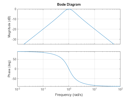
Analyzing the Response of an RLC Circuit - MATLAB & Simulink

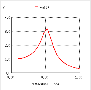
9.6: Resonant Filters - Workforce LibreTexts

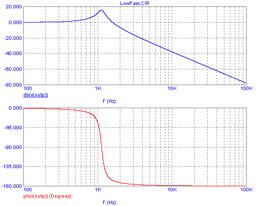
Derive and Plot a Low Pass Transfer Function on MATLAB - Technical Articles

Resonant Filters | Filters | Electronics Textbook

6: Bode diagram showing the frequency response of the RLC filter... |  Download Scientific Diagram
6: Bode diagram showing the frequency response of the RLC filter... | Download Scientific Diagram

Breakpoint Frequency - an overview | ScienceDirect Topics

Main body of Introduction

Bode diagram of LC-filter. | Download Scientific Diagram

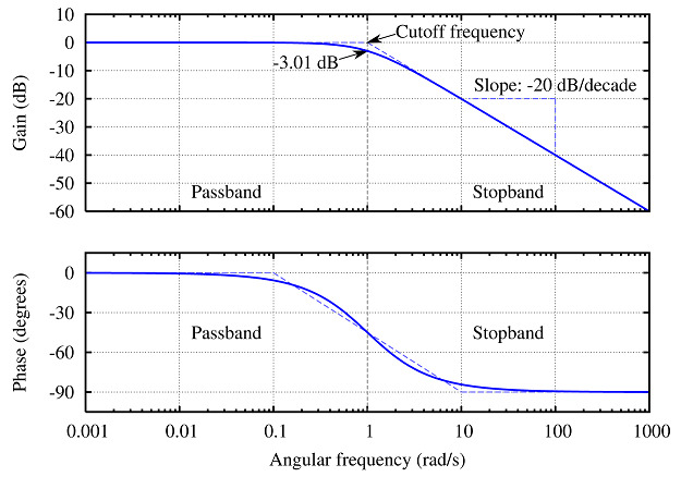
Low-pass filter - Wikipedia

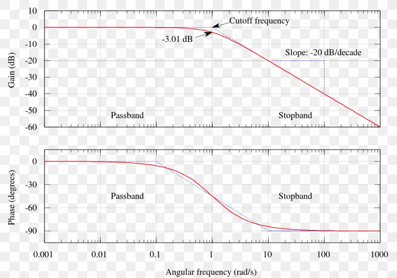
Bode Plot Low-pass Filter Butterworth Filter Decade, PNG, 1250x875px, Bode  Plot, Area, Bandpass Filter, Butterworth
Bode Plot Low-pass Filter Butterworth Filter Decade, PNG, 1250x875px, Bode Plot, Area, Bandpass Filter, Butterworth

Filter Bode-plot at different loads. | Download Scientific Diagram

Figure 5 from Virtual resistor based active damping of LC filter in  standalone voltage source inverter | Semantic Scholar
Figure 5 from Virtual resistor based active damping of LC filter in standalone voltage source inverter | Semantic Scholar

RLC Low-Pass Filter with MATLAB - Electrical Engineering Stack Exchange

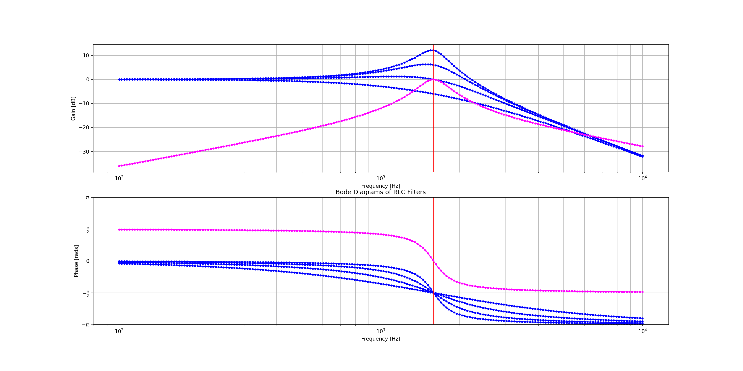
8.6.2. RLC Filter — PySpice 1.4.2 documentation

Control loops
Control loops

Filters - Low Pass and High Pass | Antique Electronic Supply

VSI LC filter optimized by a genetic algorithm from connected to island  microgrid operation | SpringerLink
VSI LC filter optimized by a genetic algorithm from connected to island microgrid operation | SpringerLink

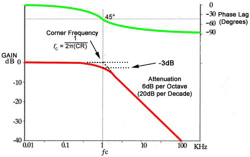
Low Pass Filter - Passive RC Filter Tutorial

Phase Response in Active Filters Part 2, the Low-Pass and High-Pass  Response | Analog Devices
Phase Response in Active Filters Part 2, the Low-Pass and High-Pass Response | Analog Devices

Bode Plots
Bode Plots

The Bode diagram of LC and LCC filter | Download Scientific Diagram

BME Signals : Signals